Wednesday, April 12, 2006

World's Strongest Glue


Caulobacter crescentus affixes itself to solid objects with its stalk and holdfast. Here, two sessile "stalk" cells (bottom) spawn mobile "swarmer" clones of themselves (top). (Photo by: Yves Brun)
A bacterium that lives in rivers, streams and human aqueducts uses nature's strongest glue to stay in one place, according to new research by Indiana University Bloomington and Brown University scientists reported in next week's (April 11) Proceedings of the National Academy of Sciences.
The scientists found they had to apply a force of about 1 micronewton to remove a single Caulobacter crescentus from a glass pipette. Because C. crescentus is so small, the pulling force of 1 micronewton generates a huge stress of 70 newtons per square millimeter. That stress, which the bacterial adhesions could sometimes withstand, is equivalent to five tons per square inch -- three or four cars balanced atop a quarter. By contrast, commercial "super" glue breaks when a shear force of 18 to 28 newtons per square millimeter is applied.
Hypothetically, C. crescentus's glue could be mass produced and used to coat surfaces for medical and engineering purposes.
There are obvious applications since this adhesive works on wet surfaces," said IU Bloomington bacteriologist Yves Brun, who co-led the study with Brown University physicist Jay Tang. "One possibility would be as a biodegradable surgical adhesive."
C. crescentus affixes itself to rocks and the insides of water pipes via a long, slender stalk. At the end of the stalk is a holdfast dotted with polysaccharides (chains of sugar molecules). The scientists show in the PNAS paper that these sugars are the source of C. crescentus's tenacity. It is presumed these sugars are attached to holdfast proteins, but this has not yet been confirmed. One thing is certain -- the polysaccharides are sticky.
"The challenge will be to produce large quantities of this glue without it sticking to everything that is used to produce it," Brun said. "Using special mutants, we can isolate the glue on glass surfaces. We tried washing the glue off. It didn't work."
The scientists allowed C. crescentus to attach itself to the side of a thin, flexible glass pipette. They used a micromanipulator to trap the cell portion of the bacterium and pull it directly away from the pipette, measuring the force of strain. In 14 trials, the scientists found they had to apply a force of 0.11 to 2.26 micronewtons per cell before the bacterium detached.
C. crescentus has evolved an ability to live in extremely nutrient-poor conditions, which explains its existence as a common fixture in tap water. Because it exists in tap water at low concentrations and produces no human toxins, C. crescentus poses no threat to human health.
Engineer L. Ben Freund wrote the model used to perform complex mathematical analyses of experimental forces. Peter Tsang and Guanglai Li of Brown University performed experiments and analyzed data. The research was funded by grants from the National Science Foundation and the National Institute of General Medical Sciences (National Institutes of Health).

Friday, March 10, 2006

Saturn Moon Spewing Water Vapors


WASHINGTON -- One of Saturn's moons, Enceladus, is spewing out a giant plume of water vapor that is probably feeding one of the planet's rings, scientists said on Thursday.
The findings, published in the journal Science, suggest that tiny Enceladus could have a liquid ocean under its icy surface which in theory could sustain primitive life, similar to Jupiter's moon Europa. The plume was spotted by Cassini, a joint U.S.-European spacecraft that is visiting Saturn.

"We realize that this is a radical conclusion -- that we may have evidence for liquid water within a body so small and so cold," said Carolyn Porco, Cassini imaging team leader at Space Science Institute in Boulder, Colorado.

"However, if we are right, we have significantly broadened the diversity of solar system environments where we might possibly have conditions suitable for living organisms."
Scientists have long known that many of Saturn's moons have water. They took an especially close look at Enceladus because it seemed to have a smooth surface -- suggesting recent geological activity that, in turn, could mean liquid water.


Liquid water is a key requirement for life. Several moons have been found to have evidence of liquid water and the chemical elements needed to make life, including Europa. But scientists are far more intrigued by the plume itself, a gigantic geyser of water vapor and tiny ice particles.

"It's basically this giant plume of gas coming out of the south pole of Enceladus," Candy Hansen of NASA'S Jet Propulsion Laboratory in California said in a telephone interview.

"The plume is half the size of the moon. It's huge," said Hansen, a planetary scientist. "Water is being spewed out of this moon. It solves some real mysteries that we have been struggling with over the years."

BUILDING BLOCKS OF LIFE

Indirect observations had shown the moon, discovered in 1789 by William Herschel, was rich in oxygen and hydrogen. But whether this was because of water was not clear.
Both water vapor and water particles were observed, as well as a smattering of other compounds such as methane and carbon dioxide, the international team of scientists report in a series of papers in Science.

It is possible the plume comes directly from ice, but more likely there is a liquid source, they said. It would have to be under the moon's surface, which is covered with ice.

"If a wet domain exists at the bottom of Enceladus' icy crust, like a miniature Europan ocean, Cassini may help to confirm it," Jeffrey Kargel of the University of Arizona at Tucson wrote in a commentary. "Might it be a habitat? Cassini cannot answer this question," Kargel added.

"Any life that existed could not be luxuriant and would have to deal with low temperatures, feeble metabolic energy, and perhaps a severe chemical environment. Nevertheless, we cannot discount the possibility that Enceladus might be life's distant outpost."

Hansen was cautious.

"I think the best you can say is there is biological potential. We have liquid water probably, and it is in contact with rocks so there are minerals," she said. "And there is energy. But we haven't detected life."

The findings help confirm theories that Enceladus was the source of Saturn's outer E-ring, the researchers said.

Saturn has at least 47 known moons. Enceladus is named after a Titan in Greek mythology who was defeated in battle and buried under Mount Etna by the goddess Athena.

Thursday, January 26, 2006

New Planet Hunting Method


A new planet-hunting technique has detected the most Earth-like planet yet around a star other than our sun, raising hopes of finding a space rock that might support life, astronomers reported on Wednesday.

"This is an important breakthrough in the quest to answer the question 'Are we alone?"' said Michael Turner of the National Science Foundation.

"The team has discovered the most Earth-like planet yet, and more importantly, has demonstrated the power of a new technique that is sensitive to detecting habitable planets," Turner said in a statement.

In the last decade, astronomers have detected more than 160 planets orbiting stars outside our solar system. The vast majority of these have been gas giant planets like Jupiter, which are hostile to life as it is known on Earth.

But an international team has detected a cold planet about 5-1/2 times more massive than Earth -- still small enough to be considered Earth-like -- orbiting a star about 20,000 light-years away in the constellation Sagittarius (The Archer), close to the center of the Milky Way.

A light-year is about 6 trillion miles, the distance light travels in a year.
To find this new planet -- named OGLE-2005-BLG-390Lb -- the team used a technique called gravitational microlensing.

OGLING A NEW PLANET

This method uses a network of telescopes to watch for changes in light coming from distant stars. If another star passes between a distant star and a telescope on Earth, the gravity of the intervening star acts like a lens and magnifies the incoming light.

When a planet is circling the closer star, the planet's gravity can add its own signature to the light, the scientists said in research being published in the current edition of the journal Nature.
This kind of light signature was observed on July 11 by a group of telescopes participating in a project known as OGLE, short for Optical Gravitational Lensing Experiment, which sees more than 500 microlensing events each year.

At first, OGLE scientists did not know that a planet was responsible for the change in the light.
They went to two other groups of telescope-using scientists, RoboNet and PLANET (Probing Lensing Anomalies NETwork), who eventually confirmed the presences of a previously unknown planet.

Astronomers have been discovering so-called extrasolar planets for the last decade, but most have used a method that looks for a characteristic wobble in stars caused by the unseen planets that orbit around them. This technique has been successful in finding Jupiter-type planets but few with Earth's mass.

However, the microlensing technique may hold promise for detecting more planets like our own, in the habitable zone neither too torridly close nor frigidly far from the stars they orbit, said David Bennett of the University of Notre Dame in Indiana, a member of the PLANET team.

"The main advantage (of microlensing) is the signals for low-mass planets: they're not weak signals, they're just rare," Bennett said by telephone. "If there happens to be a good alignment between a foreground star with its planet and the background source star, then you're able to detect that planet."

Friday, September 02, 2005

PCB Lamination Exposing & Etching (Revised)

Practical: PCB LAMINATION, ETCHING AND EXPOSING
Teacher: Mr. Babar
Lab: PCB LAB (ELECTRONICS DEPARTMENT)
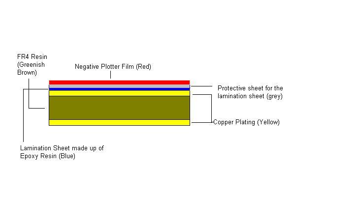

Lamination
PCB lamination is an important process in PCB manufacturing. The Lamination sheet is basically made up of epoxy resin that is a photo sensitive material. Lamination comes in the form of a sheet that is covered by protective coverings from both sides. One of these two protective sheets is removed by the laminator itself. The other one is removed after exposing it to light. Laminator is a machine that is used for providing lamination on a PCB. Basically, it totally works like a plastic coating machine. From one side, we enter our copper plated PCB (which may be drilled initially or may not be) and then, we get the fully coated (with lamination sheet) PCB from both sides. Remember! that the temperature of working can also be set in the machine and the time for the lamination is also controlled. We used a 30 sec time for our double sided PCB. The PCB is entered and we get a fully coated PCB (coated from both sides) in our hands from the other side of the laminator.

Exposing
Now, after applying this lamination, we head towards another prcoess which is th exposing process. In this process we expose our PCB towards UV light. Have a look at the state of the PCB just before exposing:


My dear friends! here comes the real confusion among the students that makes them uninterested in the subject of PCB Manufacturing. The confusion that the students usually have is to know the polarity of the films we have used in this process. By polarity i mean Positive or Negative. Now that is the reason why i have revised this article in order to make you understand the right concept. But before doing that, it is required that you free up your mind from all your previous polarity concepts and then start studying below:

There are two types of Plotter Mask. One is positive and the other is negative.

The positive plotter mask has the Tracks in Black Colour. and thus wherever the tracks are present, light cannot pass through that area. Have a look at the fig below:

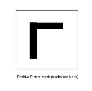
Now you can see, the tracks are in black color, so when light falls on such a mask, it passess through the white/transparent areas but get blocked from the black color.

Now, A Negative plotter mask has the Tracks in white/Transparent color, and thus wherever the tracks are present, light passess through them. Have a look at the fig below:

Now when the light will fall on such a plotter mask, it will pass through the areas of tracks only as they are transparent while the light will remain blocked from the remaining black area.

Now lets discuss the polarities of the Photoresist Films. Yeah! it is correct that the photoresist film is also of two types. Positive and Negative.

Now lets see what are these two types:

POSITIVE PHOTO RESIST:

when UV light falls on a positive photo resist film, the underlying material gets removed.

This thing must be kept in the mind. The Positive Photoresist will be used when you want to remove the material from those areas where the light is falling. So now quickly test yourself and answer my question :

What type of Plotter Mask would you use when using a Positive Photoresist Film?

Ans: Positive Plotter Mask

why? the reason is simple, you want to get copper remain on those areas where your sweet tracks are present and from other areas, the Cu should be removed. When you will use the Positive Plotter (which has black tracks) with a positive Photoresist film, the light will pass through those areas only which are other than the tracks. and hence the Cu will be removed from those areas which are other than the tracks. Lets discuss the chemistry of the positive Photo resist film a little. Actually when UV falls on such a film, it changes the chemical structure of the resist, as a result when you will put it in the developer in the developing process, it will become more soluble in the developer and thus washed away while developing it. But remember, those areas which are not exposed to light will not get soluble in the developer and thus will remain intact. This is you want!! that is you want your tracks areas to remain there. I think you now got it right? hahaha!!

NEGATIVE PHOTO RESIST:
when UV light falls on a negative photo resist film, the areas on which the UV light falls remain as it as while the areas on which the light does not fall, gets removed. Lets discuss the chemistry of it a little. When light falls on a negative photoresist film, it causes the resists to become polymerized and thus more difficult to dissolve. Thus the exposed areas remain intact during developing while the unexposed areas get removed during the developing process.

This time, you probably have guessed yourself the correct plotter mask for such film. It is right!

The plotter mask would be negative (containing tracks as transparent) so it will allow the light to pass through the tracks areas through the negative photo resist and as a result the track areas will get more difficult to dissolve and will remain as it as. The light blocked areas will get removed. Just remember the following formula:

If you want to get Cu on Tracks only as an output, you have to use

Positive Plotter Mask with Positive Photoresiste Film

Negative Plotter Mask with Negative Photoresist Film

I hope that you understand that. Even then you should have a look at the fig below:

Now! my dear friends! from now you should not have any confusion regarding this polarity issue.

If you have cleared your confusions regarding polarity, it would be better to start exposing.So, we will place it in the exposure box, Which contains tubelights on both sides that emits UV light. The box looks like a Photostate machine. The time duration is again 30 sec which can be set easily on the exposing machine.
After exposing, you will see that your image is now transferred on the PCB. It is important to understand what actually happens during exposing. The areas where UV light passes through remains unfixed while the area that remains hidden from light is fixed. As we have applied the negative plotter mask above, so it will allow light in the areas other than the tracks.

Developing
Now we are left with fixed and unfixed copper and epoxy. Now remove the plotter mask as well as the remaining protective cover of the lamination sheet which was left by the laminator. And put this PCB in the developer. Basically, developer removes the unfixed areas of epoxy. The time duration is 2 minutes here. Remember that the developer will have no effect on the fixed area of epoxy and copper.

Etching
After developing, what we are left with is the unfixed copper and the fixed copper. Surely, we would never like to remove the fixed copper area. Now our target is to remove the unfixed areas of copper. For this we use the process of etching. In etching Ferric chloride is used. It removes the unfixed areas of copper and has no effect on the fixed areas. The time for normal etching is 10 min. This can be large if your chemical is older or if your copper area is greater.

CAUSTIC Operation
After etching, what we are left with, is simply the copper tracks with fixed epoxy on their top. Now, we want to remove this fixed epoxy as well. For this we will introduce our PCB in the CAUSTIC. This caustic will remove this fixed epoxy from the top of our copper tracks as well as it will also open the holes which were covered due to this fixed epoxy.

Protection from Oxidation
After this, we will get our PCB in almost a final stage, It will be very shiny and beautiful. But it will not remain shiny and beautiful if we will not protect it from oxidation which is very much possible in open air. So we will apply a simple manual coating of LACKERS, a chemical which once coated can protect the PCB from oxidation for about a year.

Now our PCB is in our hand, apply solder mask layer and then silk screen and enjoy ur electronic creation…..

Sunday, August 21, 2005

Controlling an aeroplane using simple English commands

Aeronautics researchers at MIT have developed a manned-to-unmanned aircraft guidance system that allows a pilot in one plane to guide another unmanned airplane by speaking commands in English.

In a flight test, the pilotless vehicle, called a UAV (unmanned aerial vehicle), responded to sudden changes in plan and avoided unexpected threats en route to its destination, in real time.
"The system allows the pilot to interface with the UAV at a high level--not just 'turn right, turn left' but 'fly to this region and perform this task,'" said Mario Valenti, a flight controls engineer for Boeing who is on leave to pursue a Ph.D. in electrical engineering and computer science at MIT. "The pilot essentially treats the UAV as a wingman," said Valenti, comparing the UAV to a companion pilot in a fighter-plane squadron.


Tom Schouwenaars(left), a Ph.D. candidate in aeronautics and astronautics, and Valenti(right) are principal researchers on the guidance system, which is part of the capstone demonstration of the Software Enabled Control (SEC) program. Professors Eric Feron and Jonathan How of the Department of Aeronautics and Astronautics (aero/astro) are among the principal investigators on the SEC program.


The new guidance system is designed for volatile combat situations. For instance, a pilot might be commanded to gather images of an enemy site located in unknown territory. Rather than putting himself in danger, the pilot could assign a nearby UAV to the task. The UAV moves toward the enemy site, avoiding known threats (no-fly zones) and the unexpected (radar emanating from a missile site), all the while communicating its actions to the pilot in the other aircraft, which follows behind at a higher altitude and a safe distance. The technology also could have applications in the coordination of multiple air or space vehicles, such as in air traffic control or the reconfiguration of distributed satellite systems.

The guidance system performed flawlessly in flight tests involving a Boeing F-15 fighter jet and a Lockheed T-33 trainer fighter jet at Edwards Air Force Base in June. A pilot in the manned F-15 issued mission-level commands in everyday English--"fly to Task Area B"--to the T-33, and the T-33 executed them, maintaining a trajectory safe from threats, and at one point adjusting to a last-minute change in the predetermined mission plan. The T-33 was a substitute for the actual UAV in the test. It was manned by a pilot and crewperson who were on board to manage the aircraft in case of failure, but the vehicle was controlled entirely by MIT's software, which ran on laptops placed inside each plane.

Teaching English to an airplane


Three elements combine to make MIT's manned-to-unmanned air vehicle guidance system more flexible and more "intelligent" than previous systems. First, the team worked with Teragram Corp., a software company specializing in language technology, to create a natural-language interface through which the two vehicles communicate and coordinate their actions. The interface translates the pilot's human language into the UAV's machine language, and vice versa. "It allows us to task machines at a higher level, improving safety and efficiency," said Feron.


Second, Valenti designed a task scheduler that keeps track of the oft-changing mission data from the manned vehicle and interprets it into tasks the UAV can perform. The task scheduler is integrated with the third element, Schouwenaars' safe-trajectory-planning algorithm. The algorithm is based on mixed-integer linear programming (MILP), an optimization framework originally developed for operations research. Feron and Schouwenaars started applying MILP to the problem of aircraft routing in 2000. Unlike earlier technologies, MILP allows trajectory planning that can guarantee against collisions. Moreover, the trajectories can be computed while the vehicle is flying, requiring no pre-planning.


Using the off-the-shelf optimization software CPLEX, Schouwenaars fine-tuned the MILP-based guidance technique to enable the UAV to choose the fastest safe path to its destination--and then change course in a split second when faced with a new command or a sudden obstacle. The June flight tests marked the first time that a manned air vehicle used a MILP-based guidance system to control a UAV.


Already, said Feron, "the aerospace industry is using our system in its most advanced UAV programs." He and his team are currently working toward implementing their guidance technology in systems with multiple air vehicles. Their work is being done in MIT's Laboratory for Information and Decision Systems.

Sunday, July 10, 2005

Jet Propells...


“The magnificent jet propels air safety to new heights, yet accidents still occur. Records show that takeoff and landing remain the critical phases of flight. One long-range solution is increased automation. A Lockheed TriStar touches down ‘hands off’ at Palmdale, California; a time exposure by a remotely operated camera attached to the aircraft’s vertical tail fin blurs city and runway lights."

—From "The Air-Safety Challenge," August 1977, National Geographic magazine

Monday, June 20, 2005

Trusses: Something we should ponder on

Aslamoalaikum!

well! i was just solving my Engineering Mechanics problems related with "Trusses", suddenly, something came in my mind and i really started thinking over this very little but very important thing. So, i thought, it should be shared with you people also:

Have you observed a truss carefully, it is made up of several members working COLLECTIVELY and JOINTLY in order to bear a heavy load. Each member has some job to do. Each of them tries its level best to share its contribution in bearing the heavy load. One member alone cannot do anything effective. Its the joint effort that makes them capable of bearing a heavy load.

We Pakistanis should try to be the same, working jointly and collectively to earn developement. The Poet of the East has also said it that a person from a nation cannot do anything alone, but if a nation has unity inside it, they can touch the glories.

You see, a simple truss, can even convey to you a great lesson of unity. Now it depends upon us what we get, and what we throw...

Love Pakistan
Build Pakistan